
Table of Contents
EV Charger Maintenance: Technical Infrastructure & O&M Guide
As global electric vehicle (EV) adoption accelerates, electric vehicle supply equipment (EVSE) has evolved from simple building amenities into mission-critical infrastructure assets. However, installing hardware is only the first step. The true challenge lies in EV charger maintenance—ensuring long-term operational availability, electrical safety, and seamless user experiences across years of heavy outdoor use.
Historical industry data reveals a critical gap in EV infrastructure operations: while many Charge Point Operators (CPOs) report network availability rates between 98% and 99%, driver-reported First-Time Charge Success Rates (FTCSR) have hovered significantly lower, often around 70% to 75%. Over a third of charging failures occur on stations that appear fully operational on network maps but fail during physical plug-in, credit card processing, or high-power thermal handshakes.
This reliability gap has triggered strict regulatory enforcement globally:
- United States (NEVI Program): The National Electric Vehicle Infrastructure (NEVI) Formula Program mandates that federally funded public stations maintain a minimum 97% operational uptime per port annually. Non-compliance can result in clawed-back federal grants and loss of funding eligibility.
- European Union (AFIR): The Alternative Fuels Infrastructure Regulation imposes binding uptime, data transparency, and open payment maintenance requirements, forcing CPOs to audit both hardware and software continuous health.
- Commercial Fleets: Unscheduled charging downtime directly halts vehicle operations, triggering severe financial penalties, missed routes, and lost revenue.
Achieving high-reliability EV charging requires moving away from reactive “break-fix” approaches. Instead, operators must implement structured, preventative, and predictive EV charger maintenance programs.
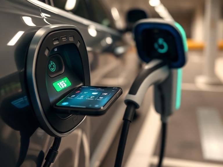
2. Anatomic Failure Modes of EV Charging Infrastructure
Understanding why chargers fail is the cornerstone of designing an effective maintenance program. EV chargers are complex electro-mechanical systems exposed to harsh weather, grid fluctuations, constant mechanical handling, and evolving vehicle software.
A. Mechanical & Physical Wear
- Cable Fatigue & Dropping: Charging cables are heavy and frequently dropped on pavement, run over by vehicles, or twisted during use. This leads to internal conductor strain, insulation tearing, and outer jacket degradation.
- Connector Pin Wear & Debris: Repeated mating cycles wear down the silver or nickel plating on CCS, NACS, or Type-2 pins. Dust, moisture, and road salt cause pin oxidation, increasing electrical contact resistance and inducing premature thermal throttling.
- Holster & Enclosure Latch Failures: Physical holsters break when cables are yanked at awkward angles, exposing sensitive connectors to rain and vandalism.
B. High-Voltage Electrical Stress
- Main Contactor Arcing & Pitting: High-power DC Fast Chargers (DCFC) use heavy-duty direct current contactors that open and close under load. Over time, electrical arcing creates surface pitting and oxidation, raising contact resistance and leading to welded contactors or failed session starts.
- Surge Protection Device (SPD) Degradation: Transient line surges from lightning or utility switching wear out internal metal-oxide varistors (MOVs). Without regular inspection, a degraded SPD leaves sensitive internal rectifiers vulnerable to catastrophic voltage spikes.
- Earth Leakage & Isolation Faults: Moisture ingress into lower conduit junction boxes degrades insulation resistance between current-carrying conductors and ground, causing Residual Current Device (RCD) or Ground Fault Circuit Interrupter (GFCI) trips.
C. Thermal & Liquid-Cooling Degradation (High-Power DCFC)
Ultra-fast chargers delivering over 150 kW to 400 kW use liquid-cooled cables to maintain manageable cable diameters and handle high currents (up to 500A+).
- Coolant Leakage & Cavitation: Glycol-based coolant loops can leak at swivel joints, cable strain reliefs, or quick-disconnect fittings. Air pockets in the coolant loop cause pump cavitation, rapid temperature spikes, and immediate emergency shutdowns during high-current charging.
- Radiator Heat Exchanger Blockage: Outdoor dust, pollen, leaves, and trash clog forced-air intake grilles and radiator fins, limiting heat dissipation and forcing the system to throttle power.
D. Software, Firmware & Protocol Breakdowns
According to industry field data, nearly half of all failed charging attempts stem from non-physical issues:
- OCPP Disconnects & Latency: Unstable cellular backhaul causes heartbeats to fail, prompting the Charging Station Management System (CPMS) to mark operational chargers as “Offline”.
- Interoperability & Firmware Incompatibility: Vehicle-to-charger handshakes fail when vehicle manufacturers release software updates that clash with older charger controller firmware.
- Payment Gateway Lockups: Unresponsive credit card readers, POS terminal connection timeouts, or expired security certificates block payment processing, leaving working chargers unusable for public drivers.
3. Maintenance Strategy Matrix: Reactive vs. Preventative vs. Predictive
Relying solely on “break-fix” maintenance guarantees prolonged downtime, high emergency repair costs, and poor driver feedback. Modern operations combine scheduled preventative inspections with real-time predictive monitoring.
| Metric / Dimension | Reactive (Break-Fix) | Preventative Maintenance (PM) | Predictive Maintenance (PdM) |
| Strategy Basis | Fix after failure occurs | Scheduled calendar/usage intervals | Real-time telemetry & ML analytics |
| Average Uptime Achieved | 80.0% – 88.0% | 95.0% – 97.5% | 98.5% – 99.9% |
| OpEx Cost Profile | High emergency repair fees | Predictable operational budget | Optimized maintenance expenditure |
| Mean Time To Repair (MTTR) | 72 – 120 Hours | 12 – 24 Hours | < 4 Hours |
| Primary Tools Used | User complaint tickets | Manual checklists, multimeters, thermal cameras | Machine learning error pattern models, automated OCPP diagnostics |
| Driver Experience Impact | Frequent session failures & poor reviews | Minor brief maintenance windows | Seamless charging experience |
By streaming live voltage, current, internal cabinet temperatures, and cable thermistor data to cloud diagnostics platforms, predictive maintenance systems flag impending hardware failures before a driver encounters a broken plug.
4. Comprehensive EV Charger Preventative Maintenance Checklist
A structured preventative maintenance schedule is essential for commercial operators, fleet managers, and site hosts. This checklist spans visual, mechanical, electrical, software, and civil checks.
A. Weekly to Bi-Weekly Inspections (Visual & Basic Upkeep)
Can be performed by site staff or facilities personnel.
- [ ] Cable & Connector Integrity: Inspect charging cables across their entire length for cracks, outer jacket fraying, twists, or exposed wiring.
- [ ] Pin & Socket Inspection: Inspect connector pins for discoloration, bent alignment, dirt build-up, or burn marks.
- [ ] Display & HMI Cleanliness: Clean touchscreens and glass covers using a soft, non-abrasive microfiber cloth and isopropyl alcohol solution. Never spray liquids directly onto screens.
- [ ] Debris & Environment Clearing: Clear leaves, trash, snow, or ice around the charging base, bollards, and air intake grilles.
- [ ] Emergency Stop Button: Confirm the visual clarity and physical freedom of the external E-Stop button.
B. Monthly Maintenance Tasks (Functional Diagnostics)
- [ ] Cable Retraction System: Test retractor counterweights or spring-tensioned overhead arms to verify cables do not drag on the ground.
- [ ] User Interface & Payment Testing: Tap test credit cards, RFID tags, and mobile app authentication to confirm payment terminal responsiveness.
- [ ] Air Intake Filter Maintenance: Clean or wash dust filters on forced-air cooled cabinets. Replace clogged filters in high-dust regions.
- [ ] Bollard & Enclosure Stability: Check cabinet mounting bolts and structural protection bollards for loose anchors or vehicle impact damage.
C. Quarterly Maintenance Tasks (Mechanical & Thermal Audits)
- [ ] Thermal Imaging Audit: Perform infrared thermography under full charging load on internal busbars, terminal blocks, contactor contacts, and cable connection points.
- [ ] Coolant Loop Verification (DCFC): Check liquid-cooling reservoir levels, inspect hoses for micro-fissures, and verify pump pressure differentials.
- [ ] Internal Ventilation Fans: Verify all cabinet intake and exhaust fans spin smoothly without bearing noise or speed drops.
- [ ] Enclosure Weather Seals: Inspect neoprene door gaskets and IP55/NEMA 4X seals for cracking or water ingress.
D. Annual Electrical & Safety Compliance Testing
Must be completed by certified high-voltage electricians or EVSE technicians.
- [ ] Insulation Resistance Testing (Megger): Measure insulation resistance between active conductors (L1, L2, L3, N) and Protective Earth (PE).
- [ ] RCD / GFCI Trip Testing: Inject simulated fault currents using an EVSE testing adapter to verify safety breaker trip times and sensitivity thresholds.
- [ ] Earthing Continuity & Resistance: Verify protective conductor resistance meets local safety regulations (typically $< 1.0\,\Omega$).
- [ ] Screw Terminal Re-Torquing: Check and re-torque all high-power electrical busbar connections to factory specifications using a calibrated torque wrench.
- [ ] Control Pilot (CP) Signal Calibration: Measure Control Pilot PWM duty cycle and voltage state levels using an oscilloscope or dedicated EVSE analyzer.
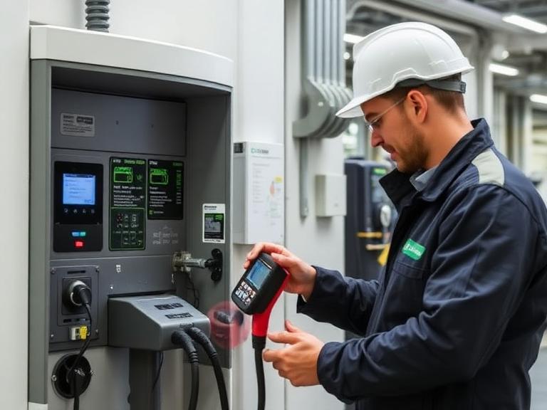
5. High-Voltage Electrical Testing & Advanced Diagnostic Procedures
When diagnosing complex faults in commercial chargers, field technicians use specialized test equipment and follow strict safety standards.
                     ┌──────────────────────────────┐
                     │   ADVANCED DIAGNOSTIC FLOW   │
                     └──────────────┬───────────────┘
                                    │
                                    ▼
                     ┌──────────────────────────────┐
                     │ Lockout / Tagout (LOTO) &    │
                     │ Zero Energy State Check      │
                     └──────────────┬───────────────┘
                                    │
                                    ▼
                     ┌──────────────────────────────┐
                     │ Connect EVSE Test Analyzer   │
                     │ (Simulate Vehicle States A-D)│
                     └──────────────┬───────────────┘
                                    │
           ┌────────────────────────┼────────────────────────┐
           │                        │                        │
           ▼                        ▼                        ▼
  ┌─────────────────┐      ┌─────────────────┐      ┌─────────────────┐
  │ Insulation Test │      │ CP/PP Pilot Check│      │ Thermal Scan    │
  │ (500V/1000V DC) │      │ (PWM Duty Cycle)│      │ Under Full Load │
  └─────────────────┘      └─────────────────┘      └─────────────────┘
A. Control Pilot (CP) & Proximity Pilot (PP) Protocol Diagnostics
The Control Pilot (CP) signal is the communication link between the EVSE and the vehicle’s On-Board Charger (OBC) or DC controller, operating on a 1.0 kHz, $\pm12\text{V}$ Pulse Width Modulation (PWM) signal per IEC 61851-1 / SAE J1772.
Voltage Level (V)
 +12V ┌──────────┐                     State A: Unplugged (+12V DC)
      │          │                     State B: Plugged In (+9V / -12V)
  +9V │          ├──────────┐          State C: Charging Requested (+6V / -12V)
      │          │          │          State D: Vent Required (+3V / -12V)
  +6V │          │          ├──────┐
   0V ┼──────────┼──────────┼──────┼─────────────── Time
 -12V └──────────┴──────────┴──────┴───────────────
Technicians use dedicated EV simulators to verify transition states:
- State A (+12V DC): Charger standby; no vehicle connected.
- State B (+9V PWM): Vehicle connected; charger ready to deliver power.
- State C (+6V PWM): Vehicle requests power; main contactor closes.
- State D (+3V PWM): Vehicle requests power with cabinet ventilation (rare).
If the pilot voltage strays outside prescribed limits (e.g., $+6\text{V}$ drops to $+4.8\text{V}$ due to resistor degradation or moisture), the charger will halt the session, resulting in a silent handshake failure.
B. Insulation Resistance (Megger) Testing
To detect insulation degradation before an arc-fault or ground breaker trip occurs:
$$\text{Target Insulation Resistance } (R_{\text{ins}}) \ge 100\text{ M}\Omega \quad (\text{at } 500\text{V or } 1000\text{V DC test voltage})$$
- Disconnect input grid power and place cabinet in a verified zero-energy state.
- Isolate sensitive internal control electronics and power modules.
- Apply 500V DC (for Level 2 AC) or 1000V DC (for DCFC) between phase conductors and protective earth for 60 seconds.
- Record readings in the maintenance log. Values falling below $10\text{ M}\Omega$ indicate water ingress, internal condensation, or insulation decay requiring immediate component replacement.
C. Infrared Thermography Audits
Under peak charging load (e.g., 300A continuous), technicians use calibrated thermographic cameras to inspect internal busbars and connections.
Temperature Delta (ΔT) = T_connection - T_ambient
- $\Delta T < 10^\circ\text{C}$ Above Ambient: Normal operating condition.
- $\Delta T = 10^\circ\text{C} \text{ to } 25^\circ\text{C}$: Moderate heating; schedule terminal torque inspection during next PM cycle.
- $\Delta T > 35^\circ\text{C}$: Severe thermal anomaly. High contact resistance risk; immediate shutdown and joint repair required.
6. Software, Firmware, and Network Telemetry Maintenance
Modern EV chargers are internet-connected computing nodes that depend on reliable software to run. Software issues account for nearly half of all service disruptions.
┌─────────────────────────────────────────────────────────────────────────┐
│               SOFTWARE & TELEMETRY MAINTENANCE LAYER                    │
├───────────────────────────────┬─────────────────────────────────────────┤
│ Remote Backend Management     │ Local Hardware Maintenance              │
├───────────────────────────────┼─────────────────────────────────────────┤
│ • Automated OCPP 2.0.1 audits │ • Cellular signal & SIM health checks   │
│ • OTA Firmware rollouts       │ • Credit card terminal key rotation     │
│ • Security patch management   │ • Offline cache buffer clear-out        │
└───────────────────────────────┴─────────────────────────────────────────┘
A. OCPP Protocol Optimization (1.6J & 2.0.1)
Charging Point Operators (CPOs) must maintain clear communication between chargers and their backend management software.
- Heartbeat Frequency: Configure heartbeat intervals (typically 300 seconds) to detect cellular drops without consuming excess data bandwidth.
- Diagnostics Log Extraction: Set up automated triggers to extract
GetDiagnostics.reqlogs whenever a charger records three consecutive failed authorization attempts. - Reset Management: Implement a tiered remote reset protocol:
- Soft Reset: Restart application software without dropping ongoing sessions.
- Hard Reset: Power-cycle cabinet microcontrollers to clear memory leaks or locked payment terminals.
B. Firmware Rollout Safeguards
Updating charger firmware fixes bugs, but poorly tested updates can disrupt charger networks.
                       ┌──────────────────────────────┐
                       │  FIRMWARE UPDATE PROTOCOL    │
                       └──────────────┬───────────────┘
                                      │
                                      ▼
                       ┌──────────────────────────────┐
                       │  Lab Staging & Interop Test  │
                       └──────────────┬───────────────┘
                                      │
                                      ▼
                       ┌──────────────────────────────┐
                       │  Canary Deploy (5% of Nodes) │
                       └──────────────┬───────────────┘
                                      │
                      ┌───────────────┴───────────────┐
                      │                               │
                      ▼                               ▼
            [Passes Success Rate]           [Failures Detected]
                      │                               │
                      ▼                               ▼
         ┌─────────────────────────┐     ┌─────────────────────────┐
         │ Fleetwide Automated     │     │ Automated Rollback      │
         │ Phased Deployment       │     │ to Baseline Firmware    │
         └─────────────────────────┘     └─────────────────────────┘
Never push over-the-air (OTA) updates to an entire network simultaneously. Follow a staged rollout process:
- Lab Staging: Test new firmware on bench units against common vehicle models.
- Canary Deployment: Deploy to 5% of non-critical chargers and monitor performance for 72 hours.
- Fleet Rollout: Expand update across the remaining network only after verifying session success rates stay above 98%.
C. Cybersecurity Maintenance
Networked chargers can be targeted for unauthorized access, service disruption, or data theft. Maintenance teams must:
- Change all factory default technician passwords during commissioning.
- Update security certificates (TLS/SSL) for OCPP connection endpoints before expiration.
- Verify physically accessible USB and Ethernet ports are disabled or password-protected inside the cabinet.
- Comply with regional directives, such as NIST guidelines in the US or CERT-In advisories in India.
7. Developing Enterprise O&M SLAs & Service Contracts
Enterprise site hosts and fleet operators should protect their investment by establishing Service Level Agreements (SLAs) with Operation & Maintenance (O&M) vendors.
┌──────────────────────────────────────────────────────────────────────────┐
│                   ENTERPRISE SLA METRICS & TARGETS                       │
├───────────────────────────┬───────────────────────────┬──────────────────┤
│ Core Service Metric       │ Performance Standard      │ Contract Penalty │
├───────────────────────────┼───────────────────────────┼──────────────────┤
│ Annual Port Availability  │ ≥ 97.0% (NEVI Standard)   │ Service Credits  │
│ Critical MTTR (DCFC)      │ < 4 Hours (Metropolitan)  │ Liquidated Dam.  │
│ First-Time Fix Rate (FTFR)│ ≥ 85.0% First Dispatch    │ SLA Reduction    │
│ Critical Spare Part Stock │ 100% Core Parts Local     │ Audit Penalty    │
└───────────────────────────┴───────────────────────────┴──────────────────┘
Essential Contract Clauses for EVSE O&M Agreements
- Uptime Calculation Formula: Ensure the contract defines uptime clearly:
$$\text{Uptime \%} = \left( \frac{\text{Total Operational Minutes} – \text{Unplanned Downtime Minutes}}{\text{Total Operational Minutes} – \text{Excluded Outages}} \right) \times 100$$
Note: Excluded outages typically include utility power blackouts, site vandalism under police investigation, or customer vehicle-side faults.
- Mean Time to Repair (MTTR) Tiers:
- Severity 1 (Entire Site Down / Safety Hazard): Technician on-site within 2 to 4 hours.
- Severity 2 (Single Fast-Charger Port Offline): Response within 12 hours; MTTR $< \text{24 hours}$.
- Severity 3 (Minor Cosmetic / Non-Critical Screen Bug): Response within 48 hours.
- Technician Training & Safety Qualifications: Require field technicians to maintain electrical safety credentials appropriate for high-voltage DC equipment (e.g., NFPA 70E compliance in North America, high-voltage vehicle/infrastructure safety certifications, and manufacturer authorization).
8. Financial Modeling: Maintenance Costs & ROI Impact
Effective maintenance protects both operational uptime and financial return on investment. Under-budgeting for ongoing maintenance leads to rapid hardware degradation and lost revenue.
Annual Maintenance Cost Benchmark (Per Port)
| Charger Type | Preventive PM Budget | Spare Parts Allowance | Software & Network Fee | Total Annual O&M Budget |
| Commercial Level 2 AC | $250 – $400 | $100 – $200 | $120 – $240 | $470 – $840 |
| Standard DCFC (50-100 kW) | $1,200 – $2,500 | $800 – $1,500 | $360 – $600 | $2,360 – $4,600 |
| Ultra-Fast DCFC (150-400 kW) | $3,000 – $5,500 | $2,000 – $4,000 | $600 – $1,200 | $5,600 – $10,700 |
                       FINANCIAL RISK OF UNMANAGED DOWNTIME
               (4-Port 150 kW DCFC Hub | $0.45/kWh Charging Tariff)

Losses / Day ($)
   $2,000 ┬─────────────────────────────────────────────────────────────────┐
          │                                                                █│
   $1,500 ┼───────────────────────────────────────────────────█────────────█│
          │                                                   █            █│
   $1,000 ┼──────────────────────────────────────█────────────█────────────█│
          │                                      █            █            █│
     $500 ┼─────────────────────────█────────────█────────────█────────────█│
          │                         █            █            █            █│
       $0 ┴─────────────────────────┴────────────┴────────────┴────────────┴
            Day 1 (Silent Bug)   Day 2 (No Tech)   Day 3 (No Part)  Day 4 (Fixed)

 Cumulative Revenue Loss: ~$4,320 + Brand Value Decline + Loss of NEVI Eligibility
Investing in proactive maintenance yields clear returns:
- Saves Revenue: Keeps high-margin DC Fast Chargers operational during peak demand periods.
- Extends Hardware Lifespan: Increases the usable service life of chargers from 5–6 years to 10+ years.
- Avoids Utility Demand Charge Spikes: Prevents miscalibrated power controllers from tripping high-peak utility demand thresholds.
9. Sector-Specific Maintenance Protocols
Different commercial sectors face distinct operational requirements and failure risks.
┌───────────────────────────────────────────────────────────────────────────┐
│                    SECTOR-SPECIFIC MAINTENANCE FOCUS                      │
├───────────────────┬───────────────────┬───────────────────┬───────────────┤
│ Fleet Depots      │ Highway Fast Hubs │ Multi-Family (MUD)│ Retail & Dining│
├───────────────────┼───────────────────┼───────────────────┼───────────────┤
│ • Nightly readiness│ • Liquid cooling  │ • RFID robustness │ • Touchscreen │
│ • Contactor stress│ • POS terminal    │ • Vandalism check │   cleanliness │
│ • Automated diagnostic│ • High utilization│ • Cable retractor │ • Easy payment│
└───────────────────┴───────────────────┴───────────────────┴───────────────┘
A. Commercial Fleet Depots (Logistics & Buses)
- Primary Objective: Ensure 100% fleet vehicle readiness for scheduled departure windows.
- Key Maintenance Focus: Heavy contactor wear testing, automated pre-flight diagnostic routines prior to shift returns, and active monitoring of liquid-cooling systems under high daily duty cycles.
B. Highway Fast-Charging Hubs (Public DCFC)
- Primary Objective: Maximize charging speeds, maintain NEVI/AFIR compliance, and ensure seamless payment processing.
- Key Maintenance Focus: Contactless credit card reader testing, screen vandalism mitigation, cable swivel repair, and radiator grille debris removal.
C. Multi-Family Residential (MUDs & Apartments)
- Primary Objective: Ensure consistent overnight charging access and reliable billing allocation.
- Key Maintenance Focus: Robust RFID access control checks, spring-retractor adjustment to keep cables off garage floors, and enclosure water protection in subterranean parking garages.

10. Frequently Asked Questions (15 Key FAQs)
1. What does routine EV charger maintenance include?
Routine maintenance covers physical inspection of cables and connectors, cleaning screen displays and air vents, testing emergency stop buttons, re-torquing internal electrical terminals, checking liquid-cooling levels, running insulation resistance tests, and updating internal firmware.
2. How often should commercial EV chargers be serviced?
Visual and basic cleaning should occur weekly or bi-weekly. Functional testing and filter cleanings should be completed monthly. High-voltage safety testing, thermal audits, and internal mechanical inspections should be performed bi-annually or annually by qualified technicians.
3. What is the NEVI 97% uptime requirement?
The US National Electric Vehicle Infrastructure (NEVI) program mandates that all federally funded public chargers maintain an average annual operational uptime of at least 97% per port. Compliance is tracked using automated software reporting systems.
4. What are the most common causes of EV charger downtime?
The leading causes of charger failure are software/firmware incompatibilities (45%), connector pin wear and cable damage (42%), OCPP network connection drops (32%), payment terminal errors (29%), and internal cooling or contactor hardware faults.
5. Can EV chargers be repaired, or do they need complete replacement?
Most EV charger failures can be repaired by replacing modular components—such as charging cables, CCS/NACS connectors, power modules, contactors, display panels, or communication boards. Entire cabinet replacements are typically reserved for severe structural damage or obsolete hardware.
6. What is the average annual maintenance cost for a commercial charger?
Annual maintenance costs average $450 to $850 per port for Level 2 AC chargers, and $2,500 to $10,000+ per port for DC Fast Chargers, depending on power rating, cooling requirements, and usage intensity.
7. How does dynamic load management affect maintenance needs?
Dynamic Load Management (DLM) software regulates power delivery across chargers to prevent electrical overloads. Maintenance teams must routinely test DLM configurations to ensure current throttling works as intended when multiple vehicles charge simultaneously.
8. Why do charging session handshakes fail when hardware looks fine?
Handshake failures usually stem from Control Pilot (CP) signal noise, worn connector pins with elevated electrical resistance, vehicle-charger firmware incompatibilities, or delayed responses from backend authorization servers.
9. What safety equipment is required for technicians servicing EV chargers?
Technicians must follow strict Lockout/Tagout (LOTO) protocols and wear appropriate personal protective equipment (PPE)—including voltage-rated rubber gloves with leather protectors, arc flash face shields, and arc-rated clothing compliant with NFPA 70E standards.
10. How do you test liquid-cooled charging cables on fast chargers?
Technicians inspect coolant reservoirs for correct fluid levels, check swivels and strain reliefs for leaks, monitor pressure differentials across circulation pumps, and run full-load thermal scans to confirm heat dissipation.
11. What is First-Time Charge Success Rate (FTCSR), and why is it important?
FTCSR measures the percentage of sessions where a driver successfully connects and starts charging on their first attempt. While a charger may report 99% uptime via basic ping tests, its FTCSR can be much lower if payment terminals or connectors are damaged.
12. How do software updates impact physical charger health?
Firmware updates fix bugs and improve vehicle compatibility. However, unverified updates can introduce new bugs or disrupt OCPP communications. Operators should test updates in a lab environment before deploying them across their charger network.
13. How do extreme weather conditions affect maintenance requirements?
Extreme heat speeds up electrical insulation wear and requires frequent filter cleanings to prevent overheating. Cold temperatures reduce cable flexibility, make plastic holsters brittle, and increase condensation risk inside cabinets, requiring robust weather seals and internal heaters.
14. What documentation should operators keep for compliance audits?
Operators should maintain digital records of all visual inspections, preventative maintenance reports, insulation resistance test logs, firmware update histories, part replacements, and automated uptime reports.
15. What is the expected operational lifespan of a commercial EV charger?
With regular preventative maintenance, commercial Level 2 and DC Fast Chargers typically last 8 to 12 years. Without proper maintenance, hardware often experiences major component failures within 3 to 5 years.



Leave a Comment