
Table of Contents
Elevator Motor Rewinding in Hyderabad | Expert Stator Repair
The traction motor serves as the prime mover of any vertical transportation system. While mechanical brakes lock the system in place and gearboxes convert rotational speeds, the electric motor generates the precise electromotive forces needed to move passengers safely between floors.
In Hyderabad’s dense commercial hubs like Madhapur and Gachibowli, alongside extensive residential zones in Kukatpally and Miyapur, elevator induction motors operate under challenging conditions. Continuous duty cycles, rapid start-stop sequences, localized voltage fluctuations, and the high humidity of the monsoon season subject the motor’s internal stator windings to severe thermal and dielectric stress.
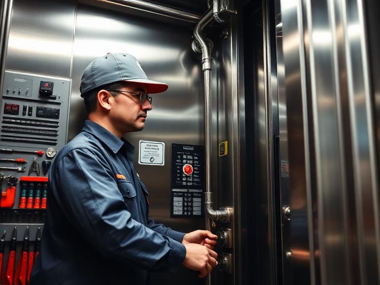
When an elevator machine room exhibits signs like an acrid chemical smell, excessive heat, constant overcurrent tripping on the variable frequency drive (VFD), or a distinct electrical hum accompanied by failure to rotate, the motor’s internal winding insulation has likely failed. Restoring these critical units requires a professional overhaul. This engineering manual outlines the diagnostics, raw materials, precise step-by-step rewinding processes, and verification testing protocols required for high-reliability elevator motor rewinding.
1. Electrical & Thermal Stress Mechanisms in Elevator Motors
Unlike standard industrial pumps or ventilation fans that run continuously at a stable speed, an elevator traction motor operates in a demanding high-cycle, start-stop manner.
Every acceleration phase subjects the stator windings to inrush currents that can be 5 to 7 times higher than normal running current. This creates significant thermal stress inside the stator slots:
ΔH∝I2Rt
This localized heat generation causes the copper wires to expand and contract relative to the laminated steel core, gradually fatiguing the thin layer of protective insulation varnish over time.
Furthermore, modern elevators use Variable Voltage Variable Frequency (VVVF) motor drives to ensure smooth ride profiles. While these VFDs improve ride comfort, their high-frequency Pulse Width Modulation (PWM) switching produces steep dv/dt voltage spikes. These microsecond surges strike the first few turns of the stator winding with high voltage, which can cause arc-overs between adjacent wire turns. If the insulation isn’t upgraded to handle these electrical stresses during a rewind, the repaired motor can quickly fail again.
2. Advanced Material Criteria: Wire Gauges and Dielectric Insulations
A high-quality rewind relies on selecting materials that can withstand these demanding electrical and thermal environments. The choice of slot liners, phase separators, magnet wire, and impregnating varnishes determines how well the motor stands up to long-term wear.
A. High-Grade Magnet Wire Selection
Standard copper wire is inadequate for traction duty cycles. Professional motor rewinding requires high-purity, oxygen-free copper wire coated with a dual-layer enamel insulation:
- Base Coat: A tough polyester-imide resin layer provides reliable mechanical strength and resistance to scraping during installation.
- Top Coat: A polyamide-imide enamel layer adds high thermal stability and chemical resistance, helping the wire maintain its properties even at peak operating temperatures.
B. Thermal Insulation Class Standards
Using low-grade Class B or Class F materials is a primary cause of premature motor failure after a rewind. Reputable workshops specify Class H insulation materials as the standard for elevator repairs.
| Insulation Class Rating | Maximum Permissible Temperature | Dielectric Breakdown Strength | Recommended Applications & Working Environment |
|---|---|---|---|
| Class B | 130∘C | Up to 4,000 Volts | Small domestic fractional-horsepower gate operator motors. |
| Class F | 155∘C | Up to 6,000 Volts | Standard commercial cargo lifts with low daily traffic cycles. |
| Class H | 180∘C | Exceeding 8,500 Volts | High-density passenger lifts, VVVF high-frequency traction systems. |
| Class N | 200∘C | Exceeding 10,000 Volts | Heavy-duty industrial miners, foundries, and steel plant freight elevators. |
C. Slot Liner and Phase Insulation Materials
The slots in the laminated iron core must be insulated with flexible sheet materials to prevent the wires from shorting to ground. High-performance repairs use Nomex-Mylar-Nomex (NMN) composites. These materials combine the structural durability of polyester film with the high thermal stability and tear resistance of aramid fibers, preventing the wires from wearing against the sharp edges of the iron core slots under heavy mechanical loads.
3. Comprehensive Technical Step-by-Step Stator Rewinding Procedure
Rewinding a multi-phase elevator motor is a highly precise process. Each step must be executed carefully to preserve the structural efficiency and electrical performance of the machine.
Precision Core Coil Insertion. Source: Southwest Electric Co.
1
Data Logging and Structural Mapping
Action Step 1
1.Data Logging and Structural Mapping:Action Step 1.
Document the motor’s nameplate specifications, including phase configurations, operating voltage, and pole count. Carefully record the original winding pattern, coil span, turn count per slot, and the exact wire gauge using a calibrated micrometer before stripping the old coils.
2
Controlled Core Burn-Off and Stripping
Action Step 2
2.Controlled Core Burn-Off and Stripping:Action Step 2.
Place the wounded stator housing into a temperature-controlled burnout oven at 360∘C to pyrolyze the old varnishes without warping the laminated core steel. Carefully pull out the degraded copper coils to prevent damaging or distorting the individual slot profiles.
3
Core Prep and Slot Liner Insertion
Action Step 3
3.Core Prep and Slot Liner Insertion:Action Step 3.
Clean the open stator slots thoroughly using wire brushes to remove all remaining scale and varnish residue. Cut Class H Nomex insulation sheets to size and slide them into each slot, ensuring they extend 5 mm past the ends of the core to provide robust ground protection.
4
Precision Coil Winding and Slot Insertion
Action Step 4
4.Precision Coil Winding and Slot Insertion:Action Step 4.
Wind new copper wire coils on automated forms to maintain uniform tension and avoid stretching the wire. Carefully insert these coil groups into the insulated stator slots one by one, keeping the wire layout neat to prevent crossover points that could lead to insulation failure.
5
Phase Bridging and Lead Connection
Action Step 5
5.Phase Bridging and Lead Connection:Action Step 5.
Separate adjacent phase coil groups using cut sheets of Nomex cloth to prevent phase-to-phase shorts. Solder the coil ends together according to the original electrical diagram, covering all joints with high-temperature silicone rubber sleeving before connecting them to the main terminal block.
6
Varnish Impregnation and Thermal Oven Curing
Action Step 6
6.Varnish Impregnation and Thermal Oven Curing:Action Step 6.
Pre-heat the fully wired stator to drive out any trapped moisture, then submerge it in a solventless epoxy impregnating varnish reservoir. Transfer the varnished unit to a curing oven at 150∘C for 4 hours to cure the resin into a rock-solid, moisture-resistant mass.
4. Post-Rewind Quality Assurance Testing Protocols
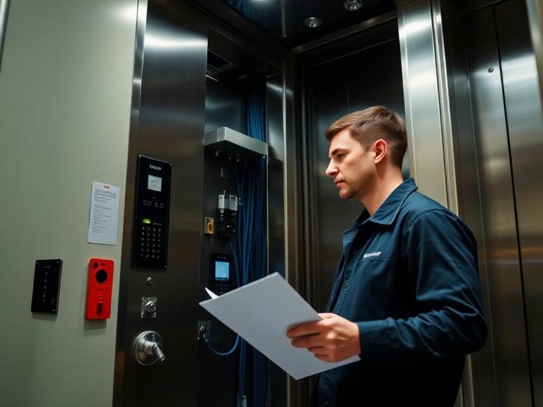
Once the physical rewinding and varnishing process is complete, the motor must pass a series of rigorous electrical and mechanical tests to ensure its safety, efficiency, and reliability before it is reinstalled.
A. Insulation Resistance Testing (Megger Evaluation)
Technicians use a digital insulation tester to check the integrity of the new insulation barriers. A test voltage of 1,000V DC is applied between the stator windings and the metal motor frame.
- The Standard: The insulation resistance must measure well above the minimum acceptable limit (100 MΩ). A low reading indicates a breakdown or pinhole leak in the slot insulation, meaning the stator cannot safely handle operating voltages.
B. High-Potential (Hi-Pot) Breakdown Testing
The Hi-Pot test checks the dielectric strength of the insulation by subjecting it to a high AC voltage to ensure it won’t arc over under peak operating stress. The test voltage is calculated using the standard industry formula:
Test Voltage=(2×Nominal Voltage)+1000V AC
For a standard 415V lift motor, a test voltage of 1,830V AC is applied across the windings for 60 seconds. The leakage current must remain below 5 mA to verify the insulation can handle voltage spikes from VFD switching.
C. Winding Resistance and Surge Comparative Analysis
Technicians use a micro-ohmmeter to measure the DC resistance of all three internal phases (U, V, and W). The measured resistance across all three windings must be tightly balanced, with less than a 2% variance between them.
Next, a surge tester applies brief high-voltage pulses to the windings, comparing the resulting wave shapes on a display screen. Identical wave patterns across all phases confirm that there are no shorted turns or internal wiring errors within the new coil groups.
5. Preventative Field Measures: Protecting the Repaired Traction Motor
A high-quality rewind restores the motor to factory specifications, but protecting that investment requires managing the operating conditions in the building’s machine room.
- VFD Parameter Recalibration: When reinstalling a rewound motor, technicians must update the VFD settings with the motor’s exact nameplate data. The drive’s current-limit parameters and acceleration/deceleration ramps should be checked to prevent excessive heat buildup during the initial startup phase.
- Machine Room Climate Control: Many elevator motor failures are caused by overheated machine rooms. Installing dedicated ventilation fans or air conditioning units to keep ambient temperatures below 38∘C helps dissipate heat from the motor frame, significantly extending the lifespan of the new insulation.
- Shaft Realignment and Bearing Maintenance: Misalignment between the motor shaft and the gearbox input coupling puts heavy radial loads on the motor bearings, causing vibration and localized heating. Aligning the shafts to within 0.03 mm and replacing worn bearings with high-quality, shielded replacements ensures smooth, quiet operation.

6. Frequently Asked Questions (FAQs)
Q1: What are the main signs that an elevator motor needs a full rewind rather than just a bearing replacement?
A: If the motor frequently trips the VFD’s overcurrent or ground fault protections, exhibits a strong burnt-insulation smell, or shows dark, charred areas inside the stator slots, the winding insulation has failed and requires a full rewind. Conversely, worn bearings typically cause a mechanical grinding noise, increased vibration, or physical shaft play while the electrical insulation values remain within safe limits.
Q2: Why is Class H insulation highly recommended for elevator motor rewinds in Hyderabad?
A: Hyderabad‘s summer temperatures, combined with the heat generated in enclosed elevator machine rooms, create demanding operating conditions. Class H insulation is rated to withstand temperatures up to 180∘C, providing an extra safety margin that protects the motor during high-traffic periods and helps prevent premature failures from overheating.
Q3: Is it possible to rewind a modern gearless permanent magnet synchronous motor (PMSM)?
A: Yes, gearless permanent magnet synchronous motors can be rewound, but the process requires specialized tools and cleanroom conditions. The powerful permanent magnets inside the rotor create strong magnetic fields that make disassembling and reassembling the motor hazardous without heavy-duty hydraulic fixtures. The stator winding patterns also require high precision to maintain proper motor torque and control.
Q4: How does a professional motor rewinding shop prevent efficiency losses after stripping the old coils?
A: To maintain original motor efficiency, the old windings should be removed using a temperature-controlled burnout oven kept below 360∘C. Using open flame torches or excessive heat can damage the thin insulation coating between the individual silicon steel laminations of the core. This increases eddy-current losses and causes the motor to run hotter and consume more power after the repair.
Q5: What is the typical turnaround time for an emergency elevator motor rewind?
A: A standard commercial three-phase induction lift motor rewind usually takes between 48 to 72 hours. This timeframe allows for proper coil winding, manual insertion, thorough varnish dipping, and the required oven-baking cycles, followed by final quality control and safety testing.
